Jolla tablet
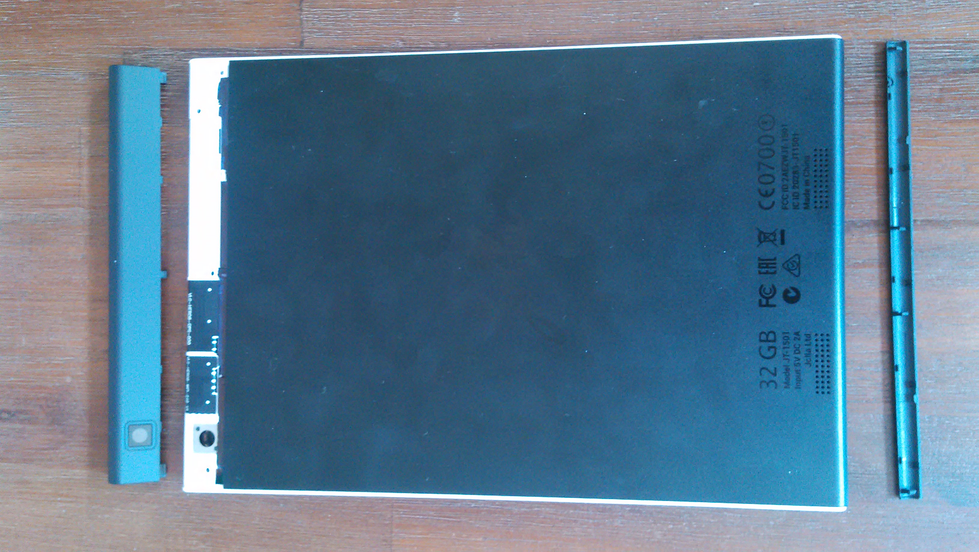
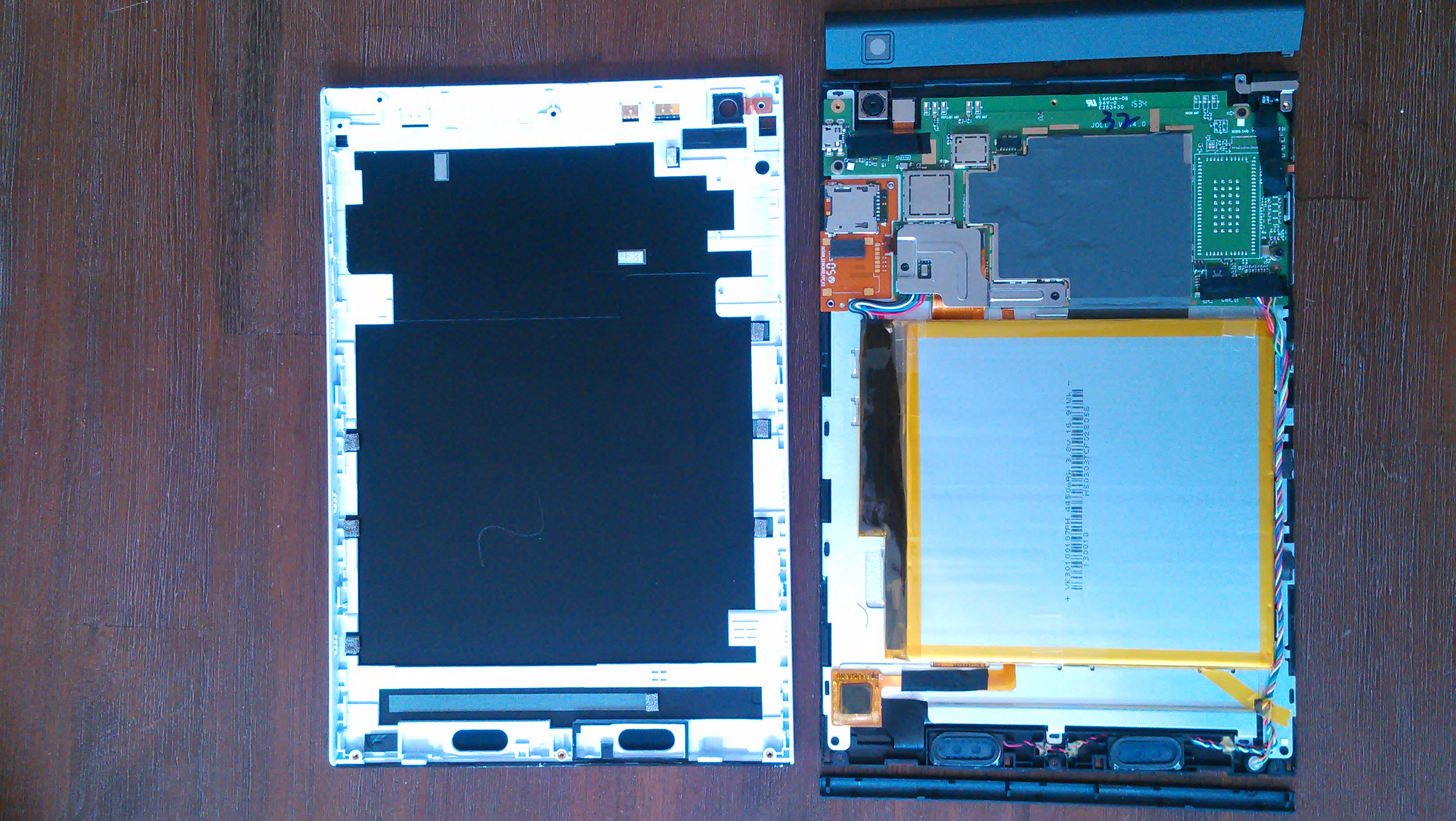
Since my (xopr's) Jolla tablet didn't boot, I opened it and took the battery out for a couple of hours. While I was at it, I took some (bad quality) pictures, and noted how to open it without breaking or bending stuff.
Contents
BIOS and booting
You can enter the UEFI BIOS by connecting USB keyboard (using USB OTG cable or adapter), and press F2 immediately after the tablet boots (by pressing the power button about 5 seconds)
To prepare the tablet for custom booting (64bit isos), you may want to enable Diagnostic spash screen in the BIOS: Main->Boot Features->Diagnostic Splash Screen = Enabled
Also note, that while the volume buttons work as arrow up/down, there is no way to enter, so you need a keyboard and (built-in) hub to accommodate for extra USB ports
To make life easier, disable secure boot, set:
Security->Set Supervisor Password(this will unlock Secure boot option)Security->Secure Boot Configuration->Secure Boot Option=Disabled- save and exit
booting from USB
Tested with a USB stick containing Ventoy:
- to enable USB boot, either press F9 at boot to skip eMMC or change boot order:
Boot->eMMC Card0: DISKto 4th place. - in Ventoy, press ctrl+r to enable grub mode
- press c to enter grub command line
- enter
systemd.unit=multi-user.targetto disable graphical menu you're about to boot - select (for example) ubuntu mate iso to run
- TODO: actual text mode boot or correct graphics mode goes here..
todo
- test which graphical modes actually carry through the display
opening the tablet
tools
You will need:
- tiny spatula-thing to pry off the plastic ends and separate the display+board from the case
- tiny philips screwdriver to remove 4 tall gray and 3 short black screws from the case, and 2 short black for the lid where the battery connector resides.
steps
- the top plastic end slides off towards the top (length of the tablet) and will reveal 4 gray screws
- the bottom plastic end can be pried off perpendicular to the screen (towards you) and will reveal 3 black screws
- the white border is attached to the back, and is clipped onto all four sides of the display/main board
- starting prying on the short ends gives a bit of space to continue on one long side
- the battery connector seems to come off perpendicular to the print (mine got torn when pulling it out adjacent to the print)
gallery
notes
The print has several interesting writings on it. From left to right:
- the back cover connector pins next to the camera modules say: WIFI/B1 ANT and GPS ANT
- SPI PRGMR (6 pin connector with black cover)
- MAIN ANT
- DEBUG CARD
- The brown SD card print has room for a SIM card, but next to the battery connector, some components are missing, so it might not be populated at all
Location: at xopr's

