Programming multicore microcontrollers
| Project: Programming multicore microcontrollers | |
|---|---|
| Featured: | |
| State | Completed |
| Members | Danny Witberg |
| GitHub | No GitHub project defined. Add your project here. |
| Description | This project describes the programming of multicore microcontrollers |
| Picture | |

| |
Contents
Introduction
Microcontroller until now were mostly single cores based, but XMOS introduced a microcontroller where multiple processes can run at once. This can be a great advantage where time critical processes can be handled simultaneously. If you want to do that on a single core microcontroller, you would have to handle the two threads with interrupts or some other means of dividing the available processing power onto the several tasks.
This project shows how multicore microcontrollers are programmed, and how several tasks are handled in an extension to the C language. It also shows how different tasks can communicate with each other, and how timed I/O can assist in achieving higher communication transfer speeds.
XMOS microcontrollers
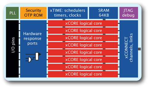
XMOS is a silicon manufacturer who specialise in multicore microcontrollers. Each chip can contain 4 to 16 XCOREs, each capable of running a seperate task. They share on chip memory, and can be connected to external I/O. An XMOS controller can also be fitted with analog capabilities, or physical interfaces like an USB PHY. Also, the XCOREs inside the microcontroller is equipped with a dedicated multiplier, ideal for performing DSP tasks. The controller runs at a decent 400MHz-500MHz and is capable of doing 1000 MIPS. With these numbers, XMOS controllers easily outperform any Arduino board, and give twice the processing power of the fastest single core microcontrollers.
XMOS controllers are programmed by a JTAG interface, and the IDE is Eclipse based. It accepts normal C/C++ programming but has an extension to the C language for handling multiprocessing instructions, XC. With these extensions parallel running tasks can be initiated and specialised I/O can be configured.
I/O : ports and clocks
I/O on an XMOS controller is regulated by ports. Each port is identified by its width, and can be multiplexed with other ports. The widths these ports come in are 32, 16, 8, 4 and 1 bit. Writing to or reading from a port means all the I/O pins are accessed at once. This is a big advantage over adressing individual pins in terms of speed. Also, a port can be configured with an internal or external clock, or a data valid signal. Buffered ports can be used to accumulate multiple I/O actions into one single bigger variable.
In the name of the port, the port width is given, so is XS1_PORT_1D a 1 bit wide port, and XS1_PORT_8B means an 8 bit port. Because there is a limited number of physical pins on the microcontroller, more than one port can be multiplexed onto the same pin. By default, port mapped with a smaller width have priority over a larger width port assigment. A one bit wide port can be configured as a clock input or output, or accompany a data port as a data valid indicator. When used in this form, a clock block indicates a group of ports which work on the same clock cycle.
Apart from these ports, pins can also be assign to a link. These link pins form a 5 bit bidirectional bus, and can be used for interconnection between multiple XMOS chips. This link bus is used for inter-process communication. This way more XCOREs can work together, even across a multi-chip system. Link buses always have priority over port mapped pins.
In XC, you can easily specify to input from a port:
in port input_port = XS1_PORT_8B;
unsigned char variable;
input_port :> variable;
The microcontroller will wait on the input instruction until data becomes available. This is because all ports are triggered by a clock block. The input for a clock block can be an 1 bit wide input port or the (divided) processor clock. An example of how an external signal can be used as a clock. You will first have to assign a clock block to be triggered by a 1 bit input port. In this example, this is the clock_port port. Next, assign the input port to use the clock block as a clock source:
in port clock_port = XS1_PORT_1A;
clock input_clock = XS1_CLKBLK_1;
configure_clk_src(input_clock, clock_port);
configure_in_port(input_clock, input_port);
Output data to a port is very similar In the following example, an 8 bit wide variable is used with a 4 bit wide output port. Only the 4 LSB's of the variable will be outputted:
out port output_port = XS1_PORT_4C;
unsigned char data_to_output = 0x0d;
output_port <: data_to_output;
A port can also be bidirectional. It acts like a normal output or input port. If you want the port to be tristated, just perform an input on the port.
port bidir_port = XS1_PORT_1F;
bidir_port <: data_to_output; // port is driven to output the LSB of the variable.
bidir_port :> variable; // same port is now tristated on the next clock cycle, and the LSB of variable now contains the port value.
Running parallel processes
The XC language extension also has instructions to run tasks in parallel to each other.
>> Insert info here <<
First project: Blinking leds
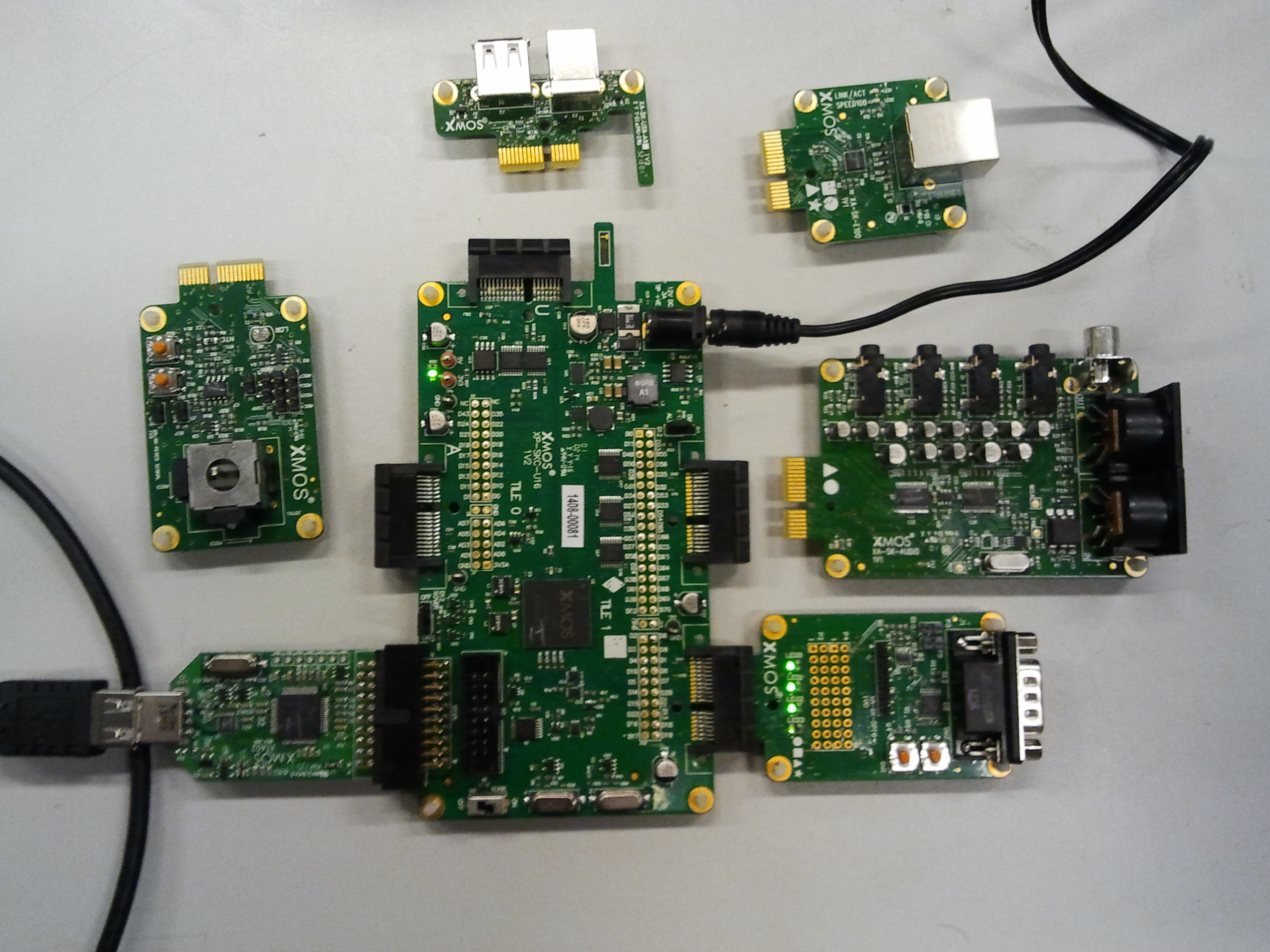
The GPIO slice is connected to the square slot on the xCORE-USB slicekit. It contains 4 leds which are connected to XS1_PORT_4A on tile 1 of the processor. We can let those leds blink as a 4 bit counter:
#include <platform.h>
#include <xs1.h>
#include <timer.h>

on tile[1]: out port ledjes = XS1_PORT_4A;

void task1(void){
 unsigned char led_status = 0;
 while (1){
  if(led_status < 16){
   ledjes <: led_status;
   led_status++;
   delay_milliseconds(50);
  } else {
   led_status=0;
  }
 }
}

int main(){
 par{
  on tile[1]: task1();
 }
 return 0;
}
