Difference between revisions of "LCD Meterkast display"
Eagle00789 (talk | contribs) |
Eagle00789 (talk | contribs) |
||
| Line 3: | Line 3: | ||
|Members=Eagle00789 | |Members=Eagle00789 | ||
|Description=Create a pcb for an LCD | |Description=Create a pcb for an LCD | ||
| − | }} | + | }} |
| − | + | == Description == | |
[[Image:Alphacool lcd.png|thumb|Alphacool lcd]][[Image:Alphacool lcd back.png|thumb|Alphacool lcd back]]The PCB is currently finished an awaiting delivery from [http://www.seeedstudio.com/depot/fusion-pcb-service-2-layers-p-835.html?cPath=70_71 Seeed Studio] for a humungus price of $32.50<br> | [[Image:Alphacool lcd.png|thumb|Alphacool lcd]][[Image:Alphacool lcd back.png|thumb|Alphacool lcd back]]The PCB is currently finished an awaiting delivery from [http://www.seeedstudio.com/depot/fusion-pcb-service-2-layers-p-835.html?cPath=70_71 Seeed Studio] for a humungus price of $32.50<br> | ||
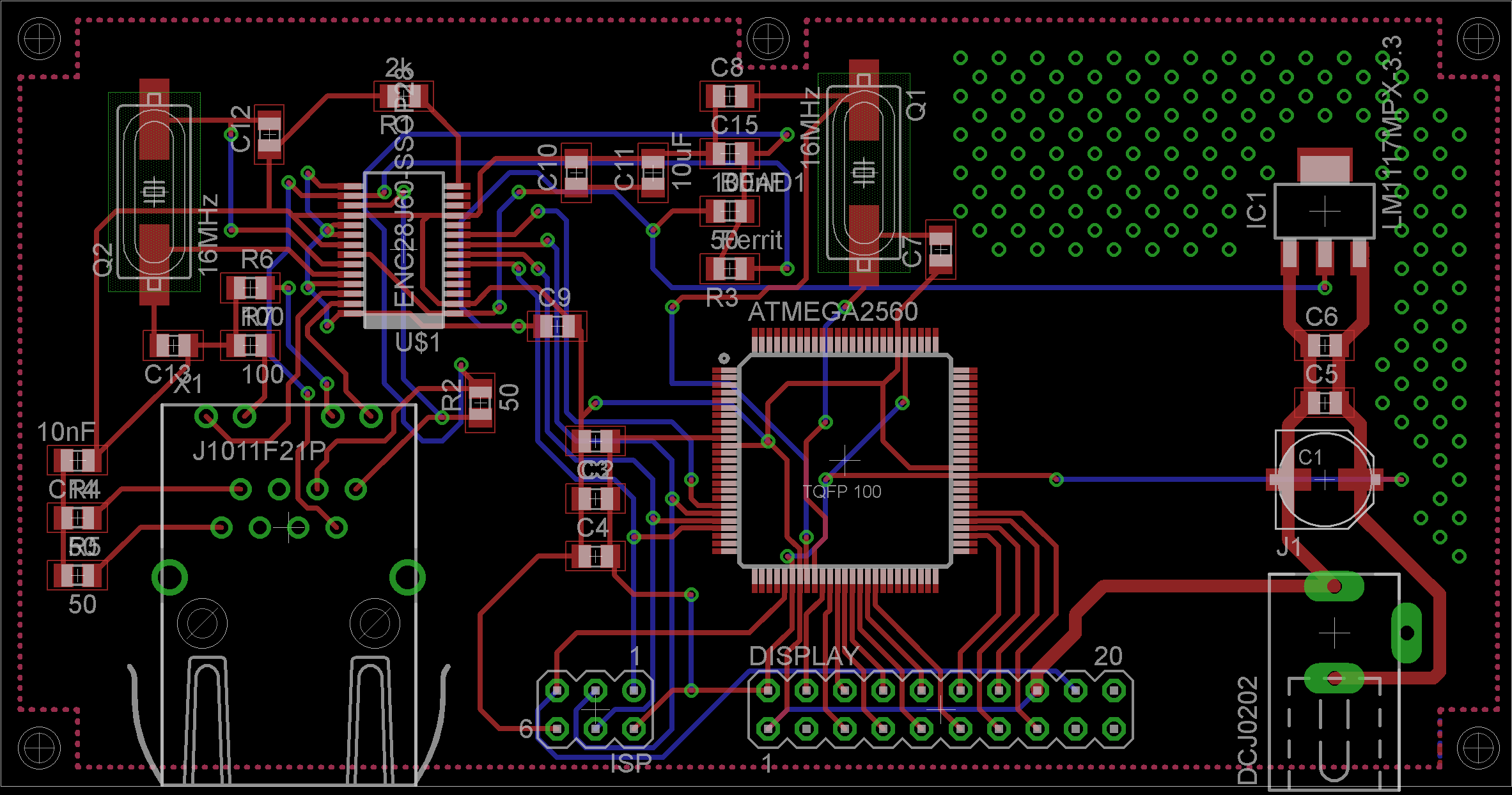
| − | To the right you can find an image of the board itself. [[Image:LCD brd.png|thumb|LCD | + | To the right you can find an image of the board itself. [[Image:LCD brd.png|thumb|LCD board]] |
On the LCD board there was already an atmega chip present. If you connect something to the LCD pins directly, you get wierd random shit or just the code residing on the atmega chip that was present on the LCD. You MUST remove this chip to connect an external source for your display in order for it to work. | On the LCD board there was already an atmega chip present. If you connect something to the LCD pins directly, you get wierd random shit or just the code residing on the atmega chip that was present on the LCD. You MUST remove this chip to connect an external source for your display in order for it to work. | ||
| + | |||
| + | == Parts == | ||
| + | === Parts needed for PCB === | ||
| + | *Alphacool LCD Display | ||
| + | *Micro-controller: ATMega 2560 | ||
| + | *Network-controller: ENC28J60 | ||
| + | *Crystal for Micro-controller: 16Mhz | ||
| + | *Crystal for Network-controller 25Mhz | ||
| + | *Network connector: J1011F21P (has embedded magnetics) | ||
| + | *3.3 volt regulator: LM117 | ||
| + | *several capacitors and resistors | ||
| + | *2 pinheaders (2x3 & 2x10) | ||
| + | *Jack connector for 5v power (required for the display) | ||
| + | *Powersupply (or modified USB cable) | ||
| + | |||
| + | === Parts removed from LCD === | ||
| + | Next to the USB Connector on the back of the LCD is a small square microcontroller. This has to be removed before you can interface with the display. | ||
| + | |||
| + | == Update == | ||
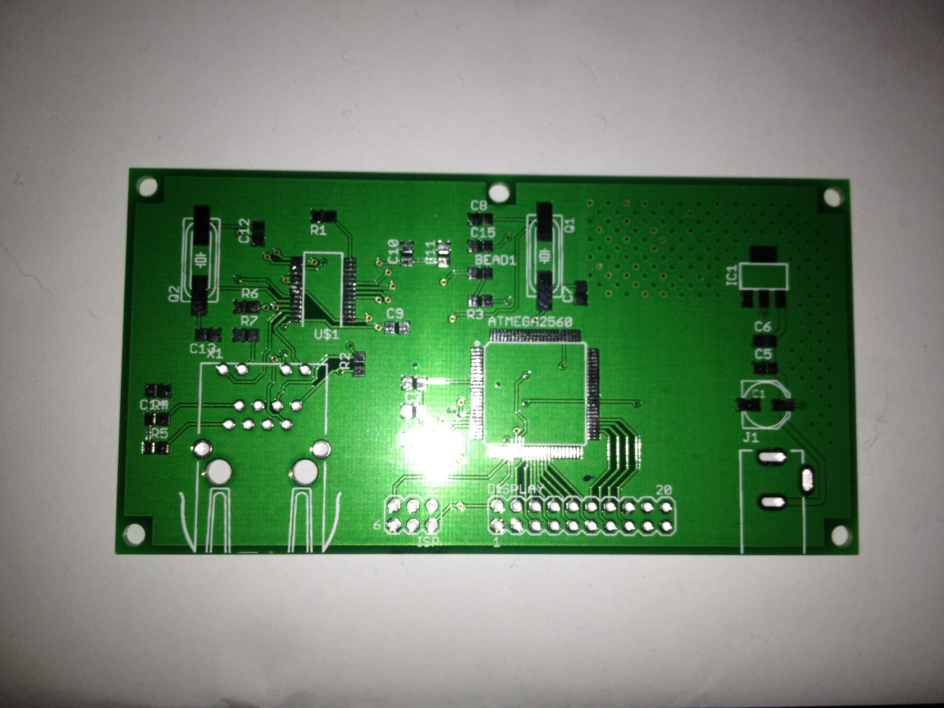
| + | I have received the finished PCB [[Image:Finished_pcb.jpg|thumb|Finished PCB]] and have placed the required components onto the pcb [[Image:Finished_pcb_with_components.jpg|thumb|Finished PCB with components]] (images can be seen to the right of this article) | ||
| + | |||
| + | === Code === | ||
| + | Currently i have the following code programmed into the microcontroller | ||
| + | <nowiki> | ||
| + | /* | ||
| + | * t6963.c | ||
| + | * | ||
| + | * Created: 31-12-2013 15:08:06 | ||
| + | * Author: eagle00789 | ||
| + | */ | ||
| + | |||
| + | #define F_CPU 1600000UL | ||
| + | #define T6963_VERSION "1.0.0.2164" | ||
| + | #include <avr/io.h> | ||
| + | #include <string.h> | ||
| + | #include "t6963c.c" | ||
| + | #include "graphic.c" | ||
| + | #include "font.c" | ||
| + | #include "Nokia_Cellphone__6.c" | ||
| + | #include "font.h" | ||
| + | |||
| + | void draw_top_left(int x, int y) | ||
| + | { | ||
| + | GLCD_SetPixel(x,y,1); | ||
| + | GLCD_SetPixel(x,y+1,1); | ||
| + | GLCD_SetPixel(x,y+2,1); | ||
| + | GLCD_SetPixel(x,y+3,1); | ||
| + | GLCD_SetPixel(x,y+4,1); | ||
| + | GLCD_SetPixel(x+1,y,1); | ||
| + | GLCD_SetPixel(x+2,y,1); | ||
| + | GLCD_SetPixel(x+3,y,1); | ||
| + | GLCD_SetPixel(x+4,y,1); | ||
| + | GLCD_SetPixel(x+1,y+1,1); | ||
| + | GLCD_SetPixel(x+1,y+2,1); | ||
| + | GLCD_SetPixel(x+2,y+1,1); | ||
| + | } | ||
| + | |||
| + | void draw_bottom_left(int x, int y) | ||
| + | { | ||
| + | GLCD_SetPixel(x,y,1); | ||
| + | GLCD_SetPixel(x,y-1,1); | ||
| + | GLCD_SetPixel(x,y-2,1); | ||
| + | GLCD_SetPixel(x,y-3,1); | ||
| + | GLCD_SetPixel(x,y-4,1); | ||
| + | GLCD_SetPixel(x+1,y,1); | ||
| + | GLCD_SetPixel(x+2,y,1); | ||
| + | GLCD_SetPixel(x+3,y,1); | ||
| + | GLCD_SetPixel(x+4,y,1); | ||
| + | GLCD_SetPixel(x+1,y-1,1); | ||
| + | GLCD_SetPixel(x+1,y-2,1); | ||
| + | GLCD_SetPixel(x+2,y-1,1); | ||
| + | } | ||
| + | |||
| + | void draw_bottom_right(int x, int y) | ||
| + | { | ||
| + | GLCD_SetPixel(x,y,1); | ||
| + | GLCD_SetPixel(x,y-1,1); | ||
| + | GLCD_SetPixel(x,y-2,1); | ||
| + | GLCD_SetPixel(x,y-3,1); | ||
| + | GLCD_SetPixel(x,y-4,1); | ||
| + | GLCD_SetPixel(x-1,y,1); | ||
| + | GLCD_SetPixel(x-2,y,1); | ||
| + | GLCD_SetPixel(x-3,y,1); | ||
| + | GLCD_SetPixel(x-4,y,1); | ||
| + | GLCD_SetPixel(x-1,y-1,1); | ||
| + | GLCD_SetPixel(x-1,y-2,1); | ||
| + | GLCD_SetPixel(x-2,y-1,1); | ||
| + | } | ||
| + | |||
| + | void draw_top_right(int x, int y) | ||
| + | { | ||
| + | GLCD_SetPixel(x,y,1); | ||
| + | GLCD_SetPixel(x,y+1,1); | ||
| + | GLCD_SetPixel(x,y+2,1); | ||
| + | GLCD_SetPixel(x,y+3,1); | ||
| + | GLCD_SetPixel(x,y+4,1); | ||
| + | GLCD_SetPixel(x-1,y,1); | ||
| + | GLCD_SetPixel(x-2,y,1); | ||
| + | GLCD_SetPixel(x-3,y,1); | ||
| + | GLCD_SetPixel(x-4,y,1); | ||
| + | GLCD_SetPixel(x-1,y+1,1); | ||
| + | GLCD_SetPixel(x-1,y+2,1); | ||
| + | GLCD_SetPixel(x-2,y+1,1); | ||
| + | } | ||
| + | |||
| + | void draw_rounded_box(int x, int y, int height, int width) | ||
| + | { | ||
| + | draw_top_left(x,y); | ||
| + | draw_bottom_left(x,y+height); | ||
| + | draw_top_right(x+width,y); | ||
| + | draw_bottom_right(x+width,y+height); | ||
| + | GLCD_Rectangle(x,y,width+1,height+1); | ||
| + | } | ||
| + | |||
| + | void draw_interface() | ||
| + | { | ||
| + | char str_output[20]={0}; | ||
| + | strcpy(str_output, "Version "); // copies "one" into str_output | ||
| + | strcat(str_output, T6963_VERSION); // attaches str_two to str_output | ||
| + | draw_rounded_box(0,0,13,239); | ||
| + | lcd_print2(60,2,"Meterkast Terminal 1", &Nokia_Cellphone__6, 0); | ||
| + | draw_rounded_box(0,114,13,239); | ||
| + | lcd_print2(75,116,str_output, &Nokia_Cellphone__6, 0); | ||
| + | draw_rounded_box(0,13,13,239); | ||
| + | lcd_print2(45,15,"Time till next update: ", &Nokia_Cellphone__6, 0); | ||
| + | } | ||
| + | |||
| + | int main(void) | ||
| + | { | ||
| + | _delay_ms(250); | ||
| + | GLCD_Initalize(); // Initalize LCD | ||
| + | _delay_ms(50); | ||
| + | GLCD_ClearText(); // Clear text area | ||
| + | _delay_ms(50); | ||
| + | GLCD_ClearCG(); // Clear character generator area | ||
| + | _delay_ms(50); | ||
| + | GLCD_ClearGraphic(); // Clear graphic area | ||
| + | _delay_ms(50); | ||
| + | GLCD_ClearGraphic(); // Clear graphic area | ||
| + | _delay_ms(50); | ||
| + | GLCD_ClearGraphic(); // Clear graphic area | ||
| + | _delay_ms(50); | ||
| + | GLCD_ClearGraphic(); // Clear graphic area | ||
| + | _delay_ms(50); | ||
| + | |||
| + | while(1) | ||
| + | { | ||
| + | draw_interface(); | ||
| + | int i; | ||
| + | for (i = 0;i < 1000;i++) | ||
| + | { | ||
| + | //lcd_print2(175,15," ", &Nokia_Cellphone__6, 0); | ||
| + | lcd_print2(175,15,"wait...", &Nokia_Cellphone__6, 0); | ||
| + | } | ||
| + | GLCD_ClearGraphic(); // Clear graphic area | ||
| + | } | ||
| + | return 0; | ||
| + | } | ||
| + | </nowiki> | ||
| + | == Current state with above code == | ||
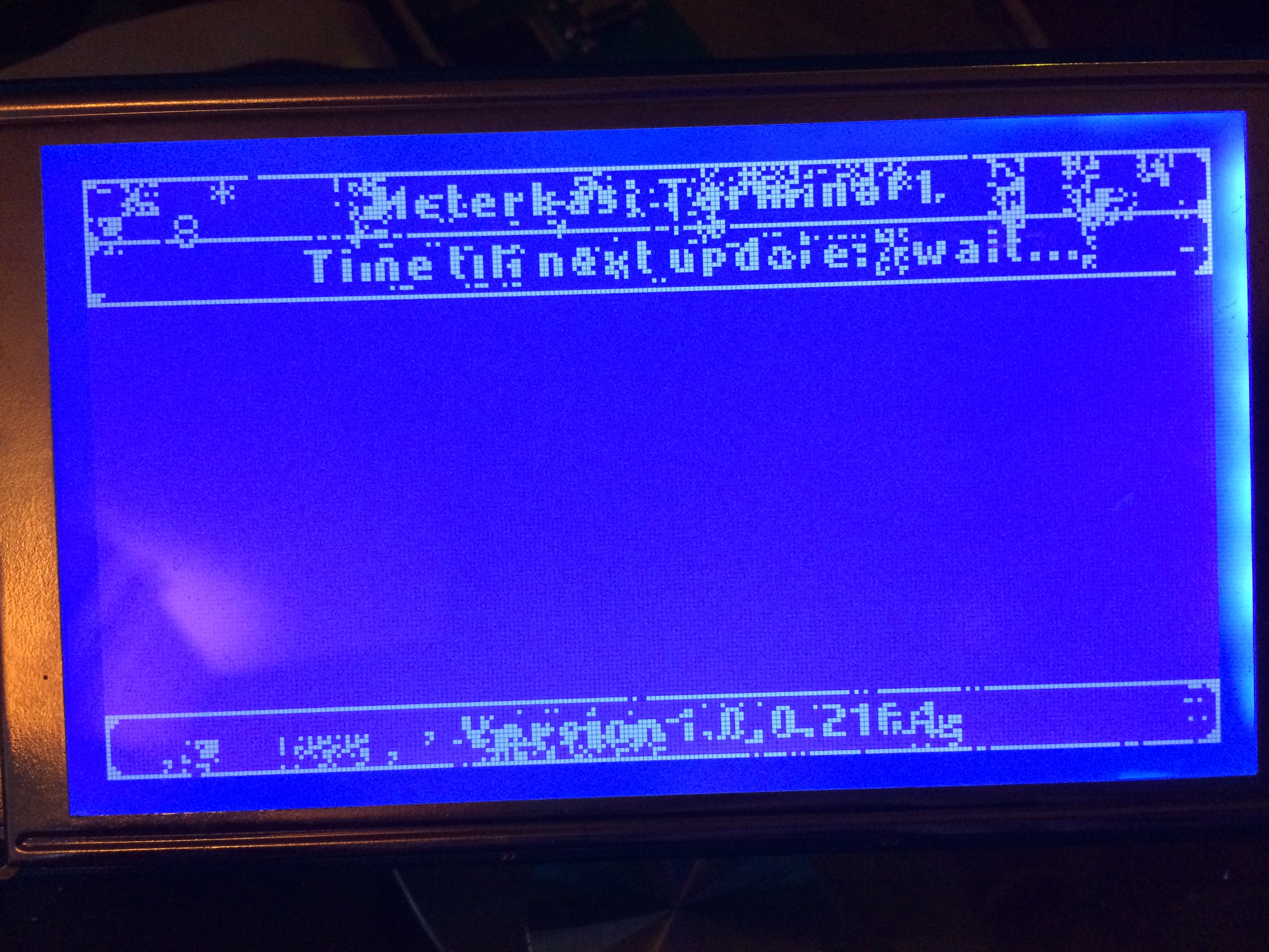
| + | The last picture on the right shows the current status of the display with the above code | ||
| + | [[Image:Working_sort_of_display.jpg|thumb|working display (sort of)]] | ||
Revision as of 02:03, 5 January 2014
| Project: LCD Meterkast display | |
|---|---|
| Featured: | |
| State | Active |
| Members | Eagle00789 |
| GitHub | No GitHub project defined. Add your project here. |
| Description | Create a pcb for an LCD |
| Picture | |
| No project picture! Fill in form Picture or Upload a jpeg here | |
Contents
Description
The PCB is currently finished an awaiting delivery from Seeed Studio for a humungus price of $32.50
To the right you can find an image of the board itself.
On the LCD board there was already an atmega chip present. If you connect something to the LCD pins directly, you get wierd random shit or just the code residing on the atmega chip that was present on the LCD. You MUST remove this chip to connect an external source for your display in order for it to work.
Parts
Parts needed for PCB
- Alphacool LCD Display
- Micro-controller: ATMega 2560
- Network-controller: ENC28J60
- Crystal for Micro-controller: 16Mhz
- Crystal for Network-controller 25Mhz
- Network connector: J1011F21P (has embedded magnetics)
- 3.3 volt regulator: LM117
- several capacitors and resistors
- 2 pinheaders (2x3 & 2x10)
- Jack connector for 5v power (required for the display)
- Powersupply (or modified USB cable)
Parts removed from LCD
Next to the USB Connector on the back of the LCD is a small square microcontroller. This has to be removed before you can interface with the display.
Update
I have received the finished PCB
and have placed the required components onto the pcb
(images can be seen to the right of this article)
Code
Currently i have the following code programmed into the microcontroller
	/*
	 * t6963.c
	 *
	 * Created: 31-12-2013 15:08:06
	 *  Author: eagle00789
	 */

	#define F_CPU 1600000UL
	#define T6963_VERSION "1.0.0.2164"
	#include <avr/io.h>
	#include <string.h>
	#include "t6963c.c"
	#include "graphic.c"
	#include "font.c"
	#include "Nokia_Cellphone__6.c"
	#include "font.h"

	void draw_top_left(int x, int y)
	{
		GLCD_SetPixel(x,y,1);
		GLCD_SetPixel(x,y+1,1);
		GLCD_SetPixel(x,y+2,1);
		GLCD_SetPixel(x,y+3,1);
		GLCD_SetPixel(x,y+4,1);
		GLCD_SetPixel(x+1,y,1);
		GLCD_SetPixel(x+2,y,1);
		GLCD_SetPixel(x+3,y,1);
		GLCD_SetPixel(x+4,y,1);
		GLCD_SetPixel(x+1,y+1,1);
		GLCD_SetPixel(x+1,y+2,1);
		GLCD_SetPixel(x+2,y+1,1);
	}

	void draw_bottom_left(int x, int y)
	{
		GLCD_SetPixel(x,y,1);
		GLCD_SetPixel(x,y-1,1);
		GLCD_SetPixel(x,y-2,1);
		GLCD_SetPixel(x,y-3,1);
		GLCD_SetPixel(x,y-4,1);
		GLCD_SetPixel(x+1,y,1);
		GLCD_SetPixel(x+2,y,1);
		GLCD_SetPixel(x+3,y,1);
		GLCD_SetPixel(x+4,y,1);
		GLCD_SetPixel(x+1,y-1,1);
		GLCD_SetPixel(x+1,y-2,1);
		GLCD_SetPixel(x+2,y-1,1);
	}

	void draw_bottom_right(int x, int y)
	{
		GLCD_SetPixel(x,y,1);
		GLCD_SetPixel(x,y-1,1);
		GLCD_SetPixel(x,y-2,1);
		GLCD_SetPixel(x,y-3,1);
		GLCD_SetPixel(x,y-4,1);
		GLCD_SetPixel(x-1,y,1);
		GLCD_SetPixel(x-2,y,1);
		GLCD_SetPixel(x-3,y,1);
		GLCD_SetPixel(x-4,y,1);
		GLCD_SetPixel(x-1,y-1,1);
		GLCD_SetPixel(x-1,y-2,1);
		GLCD_SetPixel(x-2,y-1,1);
	}

	void draw_top_right(int x, int y)
	{
		GLCD_SetPixel(x,y,1);
		GLCD_SetPixel(x,y+1,1);
		GLCD_SetPixel(x,y+2,1);
		GLCD_SetPixel(x,y+3,1);
		GLCD_SetPixel(x,y+4,1);
		GLCD_SetPixel(x-1,y,1);
		GLCD_SetPixel(x-2,y,1);
		GLCD_SetPixel(x-3,y,1);
		GLCD_SetPixel(x-4,y,1);
		GLCD_SetPixel(x-1,y+1,1);
		GLCD_SetPixel(x-1,y+2,1);
		GLCD_SetPixel(x-2,y+1,1);
	}

	void draw_rounded_box(int x, int y, int height, int width)
	{
		draw_top_left(x,y);
		draw_bottom_left(x,y+height);
		draw_top_right(x+width,y);
		draw_bottom_right(x+width,y+height);
		GLCD_Rectangle(x,y,width+1,height+1);
	}

	void draw_interface()
	{
		char str_output[20]={0};
		strcpy(str_output, "Version ");       // copies "one" into str_output
		strcat(str_output, T6963_VERSION);    //  attaches str_two to str_output
		draw_rounded_box(0,0,13,239);
		lcd_print2(60,2,"Meterkast Terminal 1", &Nokia_Cellphone__6, 0);
		draw_rounded_box(0,114,13,239);
		lcd_print2(75,116,str_output, &Nokia_Cellphone__6, 0);
		draw_rounded_box(0,13,13,239);
		lcd_print2(45,15,"Time till next update: ", &Nokia_Cellphone__6, 0);
	}

	int main(void)
	{
		_delay_ms(250);
		GLCD_Initalize(); // Initalize LCD
		_delay_ms(50);
		GLCD_ClearText(); // Clear text area
		_delay_ms(50);
		GLCD_ClearCG(); // Clear character generator area
		_delay_ms(50);
		GLCD_ClearGraphic(); // Clear graphic area
		_delay_ms(50);
		GLCD_ClearGraphic(); // Clear graphic area
		_delay_ms(50);
		GLCD_ClearGraphic(); // Clear graphic area
		_delay_ms(50);
		GLCD_ClearGraphic(); // Clear graphic area
		_delay_ms(50);

		while(1)
		{
			draw_interface();
			int i;
			for (i = 0;i < 1000;i++)
			{
				//lcd_print2(175,15,"     ", &Nokia_Cellphone__6, 0);
				lcd_print2(175,15,"wait...", &Nokia_Cellphone__6, 0);
			}
			GLCD_ClearGraphic(); // Clear graphic area
		}
		return 0;
	}
Current state with above code
The last picture on the right shows the current status of the display with the above code


