Difference between revisions of "Tiptel"
(added decoded ascii, hey, it's the version!) |
(successfully decoded several data exchange fields) |
||
| (One intermediate revision by the same user not shown) | |||
| Line 37: | Line 37: | ||
=== serial === | === serial === | ||
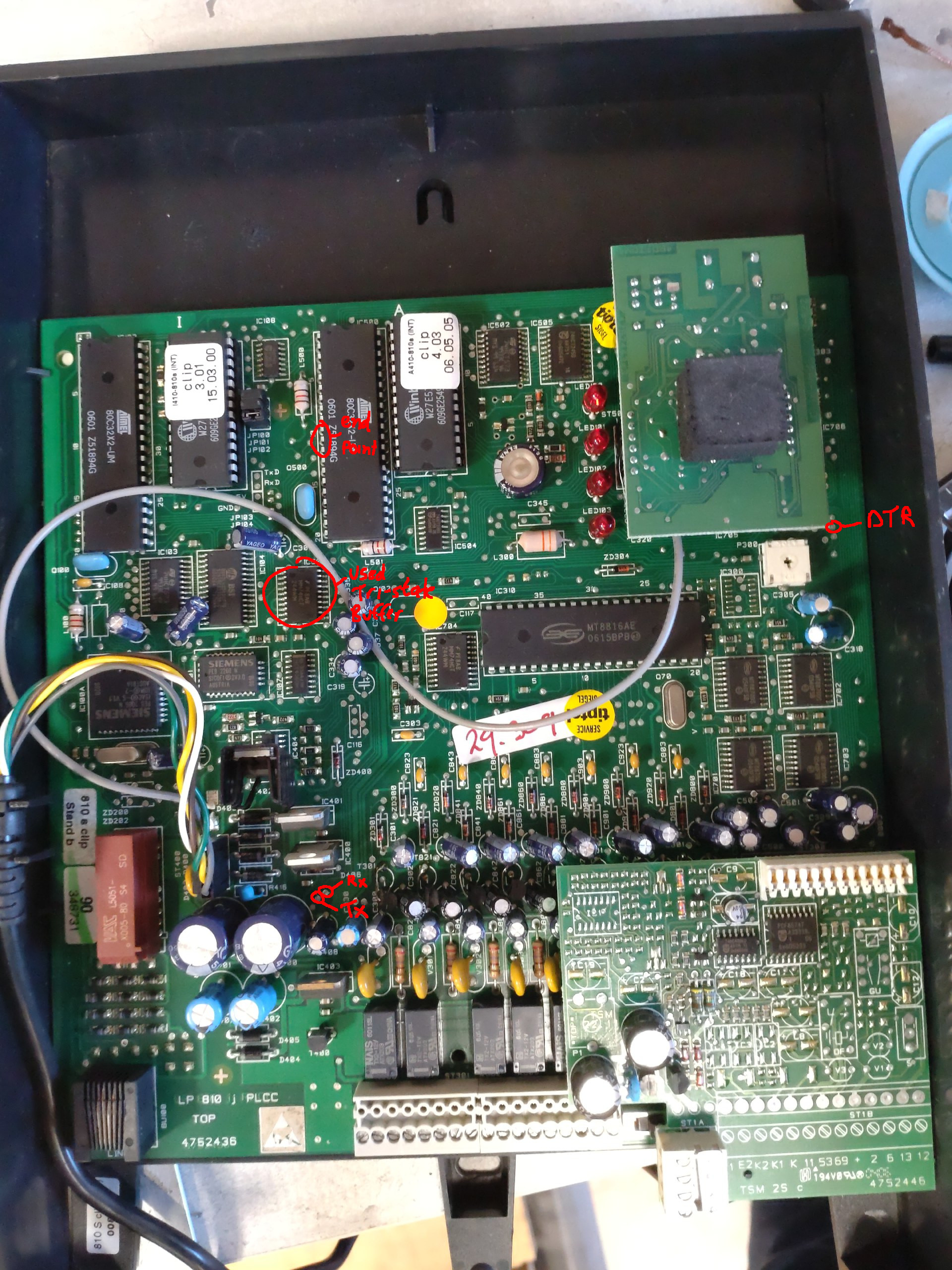
| − | * It's RS232 (non-TTL, 12V) 9600,8,n,1; you | + | [[Image:tiptel_serial_front.jpg|thumb|points to connect TTL serial (front side)]] |
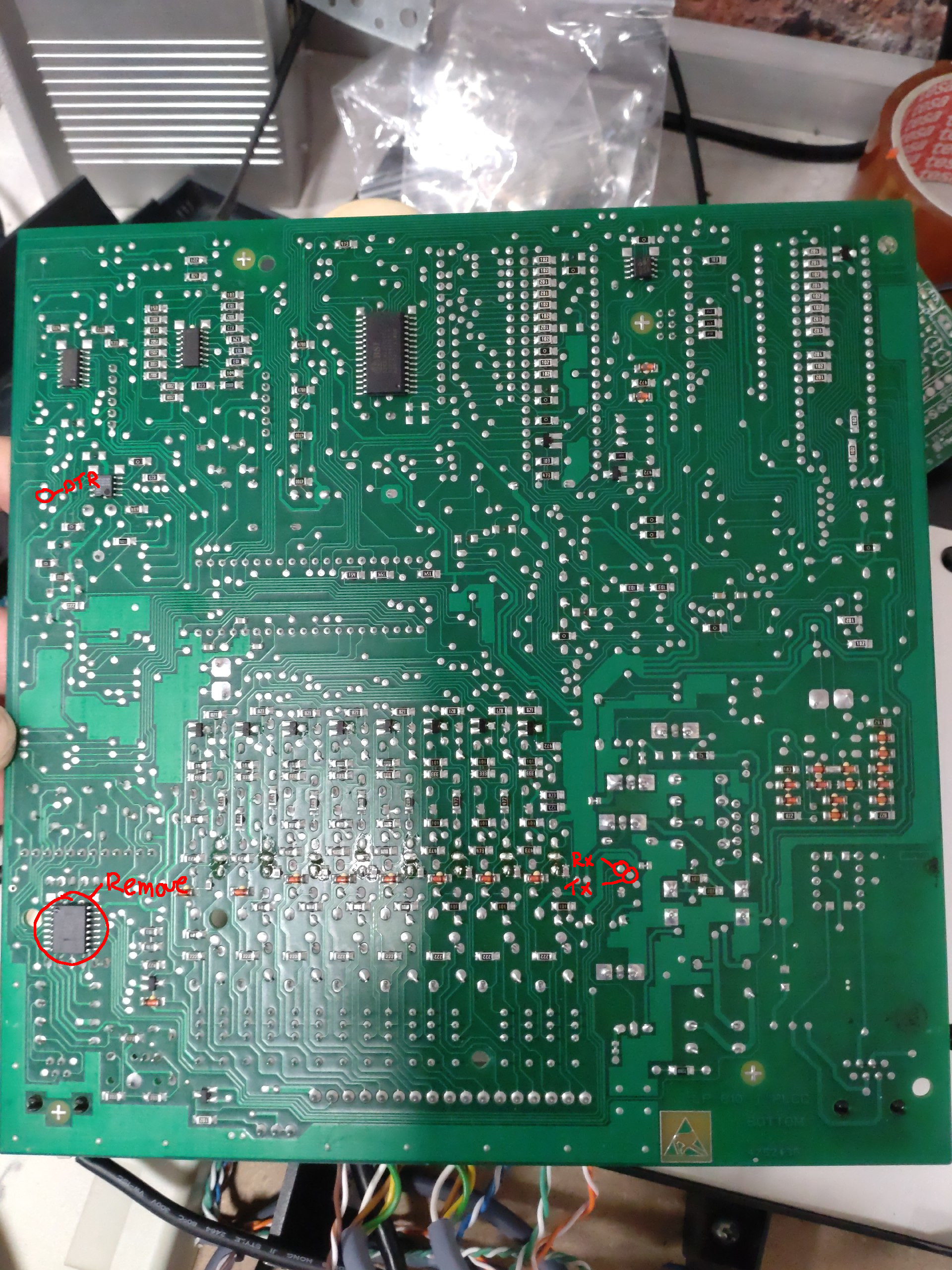
| − | * DTR is used as flow control | + | [[Image:tiptel_serial_back.jpg|thumb|points to connect TTL serial (back side)]] |
| + | * It's RS232 (non-TTL, 12V) 9600,8,n,1; you need a Max232 or genuine USB to RS232 adapter; tested with a PL2303 (note that Prolific USB drivers have not been reverse engineered on Wireshark) | ||
| + | * DTR is used as flow control (it's tied to the "extensions" (right hand side) microcontroller's interrupt0 pin via a HIN232 line driver/level shifter. | ||
* The 6P4C pinout is as followed (using female DB9): | * The 6P4C pinout is as followed (using female DB9): | ||
| Line 49: | Line 51: | ||
Tested ''tty_fake'', ''slsnif'' and ''interceptty'', but all corrupted the conection (probably due to DTR being used). | Tested ''tty_fake'', ''slsnif'' and ''interceptty'', but all corrupted the conection (probably due to DTR being used). | ||
| − | + | Experimented with wireshark USB sniffing (the serial data was not straightforward to decode): | |
* <code>modprobe usbmon</code> | * <code>modprobe usbmon</code> | ||
* <code>lsusb</code>: find the corresponding device bus and address | * <code>lsusb</code>: find the corresponding device bus and address | ||
* <code>sudo wireshark -k -i usbmon3 -Y "usb.bus_id == 33 && usb.device_address == 33 && usb.capdata"</code> | * <code>sudo wireshark -k -i usbmon3 -Y "usb.bus_id == 33 && usb.device_address == 33 && usb.capdata"</code> | ||
| − | + | Finally, wanting to use a logic analyser; I couldn't find it, tried with a makeshift Arduino as SUMP sniffer combined with Pulseview, but the buffer was way too short to do actual analysis on it. | |
| − | + | Ordered an 8-channel super cheap FX2 analyser (fx2lafw), but it needed the firmware package: <code>sudo apt install sigrok-firmware-fx2lafw</code>. | |
| − | |||
| − | + | Long story short: I used 4k7 resistors and 5v6 zeners, but still managed to short out the line driver and broke it. | |
| − | + | I removed it, found some vias that had the TTL signals and connected a Serial adapter that has RTS implemented which seems to do the job. | |
| − | |||
| − | + | === data exchange === | |
| − | + | This section still needs a lot of work but several important things have been decoded already. | |
| − | |||
| − | |||
| − | |||
| − | |||
| − | + | Steps for a message exchange: | |
| − | + | * set DTR low, wait 190mS (or the time of about 3 0x05 'heartbeat' messages) | |
| − | < | + | * send <code>attention</code> <code>length</code> <code>data..</code> <code>checksum</code>, where: |
| − | + | ** <code>attention</code> always seems <code>0x06</code> | |
| − | </ | + | ** <code>length</code> is the length of the data + checksum, 1 byte |
| + | ** <code>data..</code> is probably an EEPROM address or command (to be determined) | ||
| + | ** <code>checksum</code> is an XOR of the data only (if one byte, it'll be the same byte), 1 byte | ||
| + | * receive <code>attention</code> <code>modifier?</code>, where: | ||
| + | ** <code>attention</code> always seems <code>0x06</code> | ||
| + | ** <code>modifier</code> always seems <code>0x01</code> | ||
| + | * send <code>attention</code> | ||
| + | * receive <code>length</code> <code>addr...</code> <code>data...</code> <code>checksum</code>, where: | ||
| + | ** <code>length</code> is the length of the addr + data + checksum, 1 byte | ||
| + | ** <code>addr</code> seems 1 or 2 bytes, seems XORed with the modifier (second byte differs per response so the address or command width might be variable) | ||
| + | ** <code>data</code> might have decimal numbers mapped to hexadecimal, i.e. 0x0196 represents MSN 196 | ||
| + | ** <code>checksum</code> is an XOR of the address + data, 1 byte | ||
| + | * set DTR high and send <code>attention</code> (EOT actually) | ||
| − | + | ==== initial data ==== | |
| − | + | With the knowledge of the previous chapter, we can correlate some instructions to useful results: | |
| − | |||
| − | |||
| − | |||
| − | |||
| − | |||
| − | |||
| − | |||
| − | |||
| − | |||
| − | |||
| − | |||
| − | |||
| − | |||
| − | |||
| − | |||
| − | |||
| − | |||
| − | |||
| − | |||
| − | |||
| − | |||
| − | |||
| − | |||
| − | |||
| − | Which results in: | + | * get ISDN firmware version, write: <code>06 03 <b>80 13</b> 93</code>, eventually receive <code>15 <b>81 14</b> 00 21 05 <i>20 33 30 31 31 35 30 33 32 30 30 30</i> 02 01 00 a5 (····!·<i> 30115032000</i>····)</code> |
| + | * get analog firmware version, write: <code>06 02 <b>a0</b> a0</code>, eventually receive <code>11 <b>a1</b> 00 04 07 <i>20 34 30 33 30 36 30 35 32 30 30 35</i> b1 (····<i> 40306052005</i>·)</code> | ||
| + | Which results in the same data shown when calling PABX -> Info: | ||
<pre> | <pre> | ||
Version (I): 3.01 15.03.2000 | Version (I): 3.01 15.03.2000 | ||
Latest revision as of 12:40, 3 February 2025
Contents
synopsis
Playing with PABXes..
Tiptel 810 S clip
This is an ISDN(2) PBX with 8 extensions (of which number 8 can be set as a door intercom).
Features:
- ISDN-2 connection (RJ45), connectable with a Fritzbox' S0 port
- screw terminals
- music on hold 3.5mm jack
- serial (RS232) 6P4C connector for programming
manual
The closest I could find to get something working on the PBX is Media:Tiptel_811_Manual.pdf, but not all numbers are correct (some need to be entered as single digit).
software
After a long search, xopr found configuration software 1.11 on archive.org. He wasn't able to connect using the Windows software under Wine+Mono, but the DOS version of this software works perfectly under DOSBox
steps
- Mount the CD:
mkdir ~/tiptel;fuseiso -p ./TIP_INST_V1.11.bin ~/tiptel/ - insert USB-serial adapter, verify its address (in this example
/dev/ttyUSB0 - edit
~/.dosbox/dosbox-0.74-3.conf, look for[serial]and setserial3=directserial realport:ttyUSB0- you can also add the mounts here in the autoexec part
- the "installer" doesn't work; just run it ad-hoc (the executable looks for the translation text file)
ISDN810.EXEENGLISH/TEXT.044
- run
dosbox, mount the directory:MOUNT D /home/xopr/tiptel/DOS_SOFT/(don't forget: Ctrl+F10 to release mouse) - execute (note that it won't be able to create
ISDN810.INIon the mounted "cd"):
D:
cd ENGLISH
..\ISDN810.EXE
- select
COM3using the space bar and confirm with enter - Alt+s,n to set the MSNs (telephone numbers per extension)
- Alt+s,o to set either Telephone (allow call waiting) or modem, and check all
autom. accessfor direct ISDN access (press * switch to internal line) - upload changes: Alt+p,s
serial
- It's RS232 (non-TTL, 12V) 9600,8,n,1; you need a Max232 or genuine USB to RS232 adapter; tested with a PL2303 (note that Prolific USB drivers have not been reverse engineered on Wireshark)
- DTR is used as flow control (it's tied to the "extensions" (right hand side) microcontroller's interrupt0 pin via a HIN232 line driver/level shifter.
- The 6P4C pinout is as followed (using female DB9):
- DTR(4)+DCD(1)+RI(9)
- GND(5)
- TxD(3)
- RxD(2)
sniffing serial
Tested tty_fake, slsnif and interceptty, but all corrupted the conection (probably due to DTR being used).
Experimented with wireshark USB sniffing (the serial data was not straightforward to decode):
modprobe usbmonlsusb: find the corresponding device bus and addresssudo wireshark -k -i usbmon3 -Y "usb.bus_id == 33 && usb.device_address == 33 && usb.capdata"
Finally, wanting to use a logic analyser; I couldn't find it, tried with a makeshift Arduino as SUMP sniffer combined with Pulseview, but the buffer was way too short to do actual analysis on it.
Ordered an 8-channel super cheap FX2 analyser (fx2lafw), but it needed the firmware package: sudo apt install sigrok-firmware-fx2lafw.
Long story short: I used 4k7 resistors and 5v6 zeners, but still managed to short out the line driver and broke it. I removed it, found some vias that had the TTL signals and connected a Serial adapter that has RTS implemented which seems to do the job.
data exchange
This section still needs a lot of work but several important things have been decoded already.
Steps for a message exchange:
- set DTR low, wait 190mS (or the time of about 3 0x05 'heartbeat' messages)
- send
attentionlengthdata..checksum, where:attentionalways seems0x06lengthis the length of the data + checksum, 1 bytedata..is probably an EEPROM address or command (to be determined)checksumis an XOR of the data only (if one byte, it'll be the same byte), 1 byte
- receive
attentionmodifier?, where:attentionalways seems0x06modifieralways seems0x01
- send
attention - receive
lengthaddr...data...checksum, where:lengthis the length of the addr + data + checksum, 1 byteaddrseems 1 or 2 bytes, seems XORed with the modifier (second byte differs per response so the address or command width might be variable)datamight have decimal numbers mapped to hexadecimal, i.e. 0x0196 represents MSN 196checksumis an XOR of the address + data, 1 byte
- set DTR high and send
attention(EOT actually)
initial data
With the knowledge of the previous chapter, we can correlate some instructions to useful results:
- get ISDN firmware version, write:
06 03 80 13 93, eventually receive15 81 14 00 21 05 20 33 30 31 31 35 30 33 32 30 30 30 02 01 00 a5 (····!· 30115032000····) - get analog firmware version, write:
06 02 a0 a0, eventually receive11 a1 00 04 07 20 34 30 33 30 36 30 35 32 30 30 35 b1 (···· 40306052005·)
Which results in the same data shown when calling PABX -> Info:
Version (I): 3.01   15.03.2000
Version (A): 4.03   06.05.2005
Fritzbox connection
This documentation is a work in progress, but it is easy to accomplish.
- connect the ISDN port to S0
- set internet telephone number (or trunk/DID; shared password)
- add a PBX
todo
- tool and steps to export wireshark pcap to json, read and parse
- DTR toggle code
- actual data dissect
- Fritzbox steps

